[ad_1]

Within the fashionable busy world, the depend of automobiles enhance day-to-day and so the accidents too because of carelessness. In that manner, controlling the indicator On/Off performs a significant position in avoiding such errors. Creating an automatic car indicator management with Arduino can considerably cut back accidents and save many lives. The objective of this mission is to modify the indicator proper/left bulbs by itself and the driving force is all free from the stress.
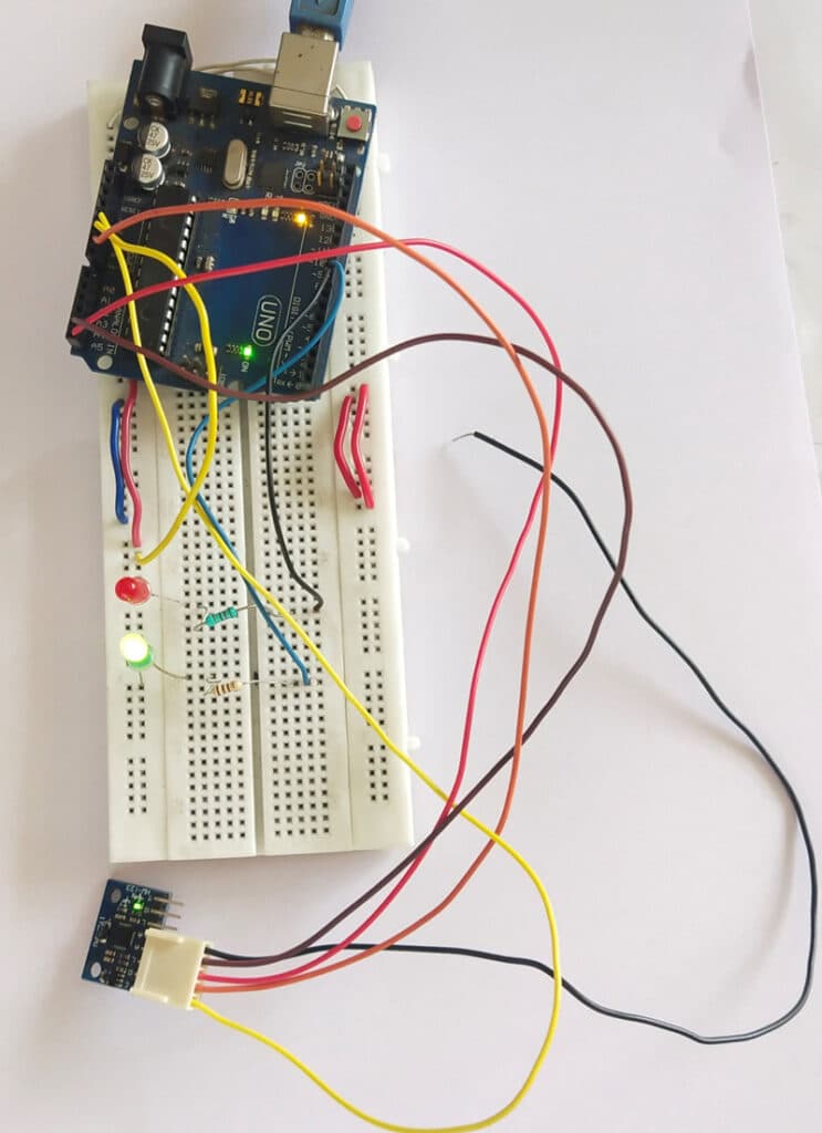
Utilizing a six-axis gyrometer cum accelerometer it’s made doable to seek out the course of motion of the four-wheeler’s steering wheel or a two-wheeler’s handlebar. At a sure diploma of motion from its origin in direction of the precise, switches the precise indicator and in direction of the left, switches the left indicator. The {hardware} and software program implementation together with establishing the MPU6050 sensor and Arduino, and programming the system utilizing Arduino IDE is defined intimately. Fig 1 shows the Writer’s prototype. Parts used within the system are listed within the invoice of supplies desk.

Invoice of Supplies:
| Parts | Description |
| Breadboard | Microcontroller for programming |
| MPU6050(MOD2) | 6-axis gyro and accelero sensor |
| Micro USB | For programming |
| Breadbord | For circuit prototyping |
| Resistors – 330R | To energy LED |
| LED | To point proper/left in prototyping |
Circuit diagram and dealing:
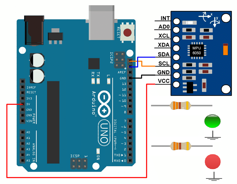
The circuit diagram of the Automobile’s proper/left indicator automated management utilizing MPU6050 and Arduino Uno is proven in Fig 2. It includes of Arduino Uno (MOD1), MPU6050 (MOD2), 330R resistors, LED and some connectors.

Software program Coding:
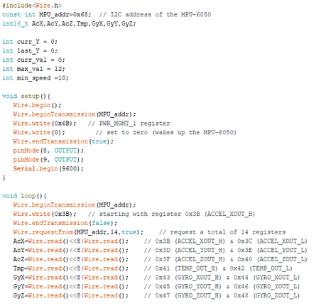
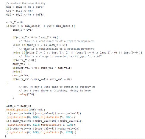
For coding use wire library (wire.h) is used for connecting and speaking with MPU6050 via I2C communication. The step-by-step coding clarification is given within the code snippet proven in Fig 3.


Within the setup perform, serial communication is initialized, setup MPU6050 sensor and the pins used for LED as Output pins.
In loop perform,
- The accelerometer and gyrometer values are learn in 3-axis
- Since it’s all about rotation, we take GyY and course of it additional.
- Min velocity is the least velocity at which the rotation is to be thought of and Max worth is a division of 360 levels. Right here I’ve used 10 as min velocity and 12 as most worth for my prototyping.
- If the learn worth comes beneath the required velocity, then the worth is moved to curr_y. The curr_y is saved in last_y earlier than leaving the loop.
- Utilizing the curr_y, the curr_val is set.
- Primarily based on the curr_val, it’s discovered whether or not the four-wheeler’s steering wheel or a two-wheeler’s deal with bar is moved in proper or left and switches the corresponding LED.
Development and Testing:
Join the sensor in response to the circuit diagram proven in Fig 2, add the code to the board, and energy the system with a USB cable or 5V battery. Now make a change within the place of the prototype wheel. The corresponding LED lights up.
V. Shelvaraj is a Technical Director at TRY WIN TECH
[ad_2]