[ad_1]

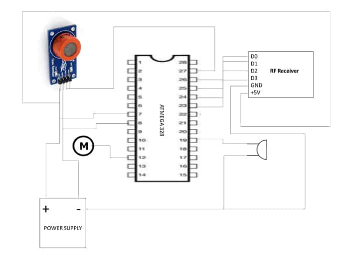
This proposed system goals to handle the shortcomings of the present system by using cutting-edge know-how to scale back highway accidents brought on by over-speeding and drunk driving. The system consists of an RF module, an MQ3 alcohol sensor, and a microcontroller to measure the car’s velocity and the motive force’s blood alcohol content material. The information collected is then processed, and if the motive force is discovered to be underneath the affect of alcohol, the system prevents ignition, and if the car is discovered to be over-speeding, the velocity is routinely managed to adjust to the posted velocity restrict.
Parts Required
1. RF Module: The RF module is used to wirelessly transmit knowledge between the car and the management heart. It’s able to sending and receiving knowledge over a distance of as much as 100 meters.
2. MQ3 Alcohol Sensor: The MQ3 sensor is used to measure the motive force’s blood alcohol content material. It’s a fuel sensor that detects ethanol, the first part of alcoholic drinks.
3. Microcontroller: The Atmega 328 microcontroller is used to manage the system’s total performance. It processes the info collected by the RF module and the MQ3 sensor and makes use of it to manage the car’s velocity and forestall ignition if essential.
Working
The proposed system works by first measuring the car’s velocity utilizing the RF module. This knowledge is then in comparison with the posted velocity restrict, and if the car is discovered to be over-speeding, the system routinely controls the velocity to conform with the restrict.
Concurrently, the MQ3 sensor measures the motive force’s blood alcohol content material. If the stage is above the authorized restrict, the system prevents ignition, and the car can not be began till the motive force’s alcohol stage drops under the authorized restrict.
If the motive force’s alcohol stage is under the authorized restrict, the system permits ignition, and the car may be began. Nevertheless, if the motive force’s alcohol stage exceeds the authorized restrict whereas driving, the system will alert the motive force and routinely management the velocity to stop accidents.
Connection Diagram

Coding
#embody <LiquidCrystal.h> #outline set off 8
#outline echo 7
#outline motor 6
#outline buzzer 13
#outline bm2 10
#outline rf0 A0
#outline rf1 A1
#outline rf2 A2
#outline rf3 A3
#outline al A4
LiquidCrystal liquid crystal display(12, 11, 2, 3, 4, 5); float time = 0, distance = 0; int studying;
int velocity=0;
int temp = 0;
void setup()
{
liquid crystal display.start(16, 2);
pinMode(set off, OUTPUT); pinMode(echo, INPUT);
pinMode(buzzer, OUTPUT); pinMode(bm2, OUTPUT);
pinMode(rf0, INPUT);
pinMode(rf1, INPUT);
pinMode(rf2, INPUT);
pinMode(rf3, INPUT);
pinMode(al, INPUT);
liquid crystal display.print("SPEED COTROL AT"); liquid crystal display.setCursor(0, 1);
liquid crystal display.print("SENSITIVE ZONES"); delay(3000);
studying = digitalRead(al);
if (studying==LOW)
{
digitalWrite(buzzer,1);
analogWrite(motor,0);
liquid crystal display.clear();
liquid crystal display.print("ALCOHOL DETECTED"); liquid crystal display.setCursor(0, 1);
liquid crystal display.print("VEHICLE STOPPED"); delay(1000);
whereas(digitalRead(al) == 0){} }
}
void loop()
{
digitalWrite(rf0, HIGH);
digitalWrite(rf1, HIGH);
digitalWrite(rf2, HIGH);
digitalWrite(rf3, HIGH);
liquid crystal display.clear();
liquid crystal display.print("SPEED COTROL AT"); liquid crystal display.setCursor(0, 1);
liquid crystal display.print("SENSITIVE ZONES"); delay(200);
digitalWrite(bm2, LOW);
digitalWrite(buzzer, LOW);
delayMicroseconds(2);
digitalWrite(motor,1);
temp = 0;
studying = digitalRead(rf0);
if (studying==LOW)
{
 velocity=150;//
digitalWrite(buzzer,1);
analogWrite(motor,velocity);//
liquid crystal display.clear();
liquid crystal display.print("SCHOOL ZONE");
liquid crystal display.setCursor(0, 1);
liquid crystal display.print("60KM SPEED PLEASE"); delay(1000);
whereas(digitalRead(rf0) == 0){} }
analogWrite(motor,velocity);//
studying = digitalRead(rf1);
if (studying==LOW)
{
 velocity=120;
digitalWrite(buzzer,1);
analogWrite(motor,velocity);
liquid crystal display.clear();
liquid crystal display.print("HAIR PIN BEND"); liquid crystal display.setCursor(0, 1);
liquid crystal display.print("30KMS SPEED");
delay(1000);
whereas(digitalRead(rf1) == 0){}//modified }
analogWrite(motor,velocity);
studying = digitalRead(rf2);
if (studying==LOW)
{
 velocity=75;
digitalWrite(buzzer,1);
analogWrite(motor,velocity);
liquid crystal display.clear();
liquid crystal display.print("OVER BRIDGE");
liquid crystal display.setCursor(0, 1);
liquid crystal display.print("10KMS SPEED");
delay(1000);
whereas(digitalRead(rf2) == 0){}
}
analogWrite(motor,velocity);
studying = digitalRead(rf3);
if (studying==LOW)
{
digitalWrite(buzzer,1);
analogWrite(motor,0);
liquid crystal display.clear();
liquid crystal display.print("Hazard");
liquid crystal display.setCursor(0, 1);
liquid crystal display.print("ZONE DETECTED");
delay(1000);
whereas(digitalRead(rf3) == 0){}
}
studying = digitalRead(al);
if (studying==LOW)
{
digitalWrite(buzzer,1);
analogWrite(motor,75);
liquid crystal display.clear();
liquid crystal display.print("ALCOHOL DETECTED");
liquid crystal display.setCursor(0, 1);
liquid crystal display.print("SPEED REDUCED..");
delay(1000);
whereas(digitalRead(al) == 0){}
}
}
This code makes use of an Arduino board linked to a number of sensors and actuators. The board is linked to a LiquidCrystal show and an ultrasonic sensor with a set off and echo pin, in addition to a buzzer, a motor, and a number of enter sensors together with 4 pins of RF modules (rf0-rf3) and an alcohol sensor (al). The code makes use of these sensors to manage the velocity of the motor primarily based on the readings from the proximity sensors, show messages on the LCD, and detect alcohol within the setting.
Conclusion
The proposed system gives a dependable and efficient strategy to scale back highway accidents brought on by over-speeding and drunk driving. By using superior know-how, the system can precisely measure the car’s velocity and the motive force’s blood alcohol content material and routinely management the velocity to adjust to the posted velocity restrict and forestall ignition if essential. This method has the potential to make a vital affect on highway security and save numerous lives, and we hope that it’ll be carried out on a wider scale sooner or later.
[ad_2]