[ad_1]

A rain alarm, also called a rain sensor or rain alarm system, is a tool that may have numerous utilities relying on its design and meant use.
Listed below are some widespread makes use of and advantages of a musical rain alarm:
1. Irrigation Management: Many agricultural and landscaping methods use rain alarms to routinely flip off irrigation methods when it rains. This conserves water and prevents overwatering, which may be dangerous to vegetation.
2. Automated Window Closure: Some rain alarms are built-in into sensible house methods to shut home windows and skylights when it begins to rain routinely. This may also help forestall injury on account of rain-water and keep indoor consolation.
3. Rainfall Monitoring: In meteorology and hydrology, rain alarms are used to observe and document rainfall information. This info is important for climate forecasting, flood prediction, and water useful resource administration.
4. Out of doors Occasion Planning: For outside occasions like weddings, concert events, and sports activities video games, a musical rain alarm can be utilized to observe the climate. It might probably set off an alert or music to warn occasion organizers and contributors of impending rain to allow them to take applicable motion.
5. Car Alert: In some instances, rain alarms may be put in in automobiles to supply drivers with real-time details about rain depth. This may be helpful for making driving choices and enhancing security.
6. Gardening: Gardeners typically use rain alarms to trace rainfall and watering wants. They’ll arrange automated watering methods which are triggered by the rain alarm information.
7. Roof leak detection: Rain alarms may be put in in attics to detect roof leaks. If water begins to enter the attic on account of a leaky roof, the alarm can alert owners to the problem.
8. Conservation: Rain alarms can encourage water conservation by signaling when rain is falling, prompting people to show off taps, sprinklers, and different water-consuming gadgets.
9. Pool upkeep: For pool homeowners, rain alarms may also help handle water ranges. When it rains, they are often programmed to routinely drain extra water from the pool to forestall overflows.
10. Instructional functions: Rain alarms are typically utilized in instructional settings to show college students about climate and local weather ideas, similar to precipitation measurements and information assortment.
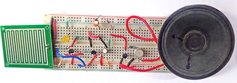
The utility of a musical rain alarm relies on its particular utility and the way it’s built-in into numerous methods and processes. The creator’s prototype is proven in Fig. 1.

| Rain Alarm Elements Record | |
| Semiconductors: | |
| IC1 | -LM7805, 5V voltage regulator |
| IC2 | -UM66 melody generator |
| T1 | -BC547 NPN transistor |
| T2 | -BC548 NPN transistor |
| T3 | -2N2219 NPN transistor |
| T4 | -SL100 NPN transistor |
| BR1 | -1A bridge rectifier |
| LED1 | -5mm crimson LED |
| LED2 | -5mm yellow LED |
| Resistors (all 1/4-watt, ±5% carbon): | |
| R1 | -1-kilo-ohm |
| R2 | -220-kilo-ohm |
| R3, R4, R7 | -220-ohm |
| R5, R8 | -10-kilo-ohm |
| Capacitors: | |
| C1 | -1000μF, 35V electrolytic |
| C2 | -1000μF, 16V electrolytic |
| C3 | -220μF, 16V electrolytic |
| Miscellaneous: | |
| CON1, CON2 | -2-pin connector |
| LS1 | -8Ω, 0.5-watt speaker |
| X1 | -230V AC main to 9V, 500mA secondary transformer |
| RS | -Rain sensor |
Rain Alarm Circuit
The circuit diagram of the musical rain alarm is proven in Fig. 2. The guts of this system is a rain sensor linked throughout CON2. The circuit contains step-down transformer X1, bridge rectifier BR1, 5V voltage regulator LM7805 (IC1), rain sensor (RS), 4 NPN transistors (T1 by means of T4), melody generator UM66 (IC2), speaker (LS1), 3.1V zener diode, and some different elements.

This system operates with 5V DC, which is derived from the 230V AC main to 9V, 500mA step-down transformer X1. The 230V AC Mains is linked to the first of X1 through CON1 within the circuit. The secondary of X1 is at 9V AC, which is linked to the bridge rectifier BR1 for rectification and filtered by capacitor C1. The rectified 5V is given to the rain sensor and the circuit to function.
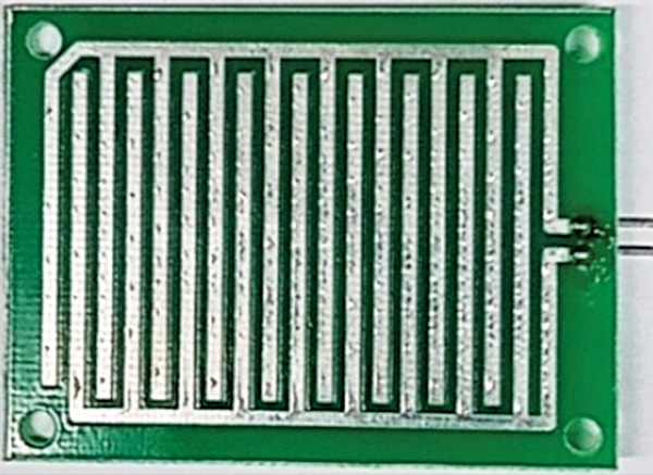
On this circuit, we’re interfacing a musical rain sensor with the melody IC UM66. Now we have used two LEDs within the circuit; one (LED1) is for the ability provide indicator, and the second (LED2) is yellow, indicating that rain is continuous. Fig. 3 exhibits the picture of the rain sensor used right here. It has two terminals that want to attach throughout CON2 throughout set up.

Working
When the rain begins, the sensor gives a constructive voltage at level ‘B,’ which makes transistor T2 to conduct. The capacitor C2 then expenses and transistor T3 conducts; IC2 will get 3.1V to allow the melody generator sound through transistor T4 and the speaker. On the identical time, transistor T1 additionally conducts, and the yellow LED glows to point the standing of rain.
Rain Alarm Circuit PCB Design
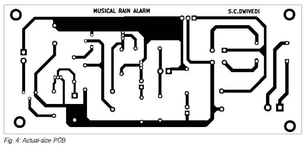
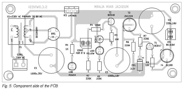
An actual-size, single-side PCB structure for the musical rain alarm is proven in Fig. 4, and its part structure is proven in Fig. 5. After assembling the circuit on the PCB, enclose it in an acceptable field. Repair LED1, LED2, and CON2 on the entrance aspect of the field and the mains energy connector CON1 on the rear aspect of the field.


Join two pins of the rain sensor with twin wires and set up it on the roof in such a means that raindrops ought to fall on it. Join the opposite ends of the dual wires to CON2 on the PCB.
Bonus: You’ll be able to watch the video of the tutorial of this DIY undertaking at https://www.electronicsforu.com/videos-slideshows/live-diymusical-rain-alarm
S.C. Dwivedi is an electronics fanatic and circuit designer at EFY
[ad_2]