[ad_1]

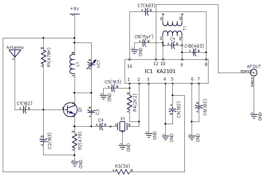
Right here is an easy circuit diagram of 88-108 MHz FM Radio Receiver Circuit diagram. The circuit may be very easy and the parts used on this circuit might be simply out there in a market and in addition the fee is reasonable additionally.
This circuit works on a preferred built-in circuit KA 2101.T1 works for RF Amplifier, Oscillator 93-113.5 MHz and mixer. And KA 2101 works for five.5 MHz IF amplifier FM detector and AF preamplifier. A circuit diagram of AF amplifier shouldn’t be given right here however you need to use TBA 810 (7 watt), e.t.c. The TBA 810 (7 watt) will efficiency good and high quality sound output. You might also use 5.5 MHz ceramic filters within the state of 5.5 MHz IFT coils which is able to remove of tunning IFT coil and distortion.

Circuit Description
Transistor Q1 BF 494 is a excessive frequency transistor and can works right here as RF amplifier, oscillator (5.5MHz increased than 88.00MHz-108MHz) and a mixer. A Coil L1 is a 23 SWG wire wound on 5mm air core with 5 turns. This coil and a 2-22pF trimmer will make an oscillation of frequency 5.5MHz increased than 88.00MHZ and 108.00MHz. A 5.5MHz output sign from emitter of Q1 is handed to a 5.5MHz IF enter stage of IC1 KA2101 utilizing a capacitor C4 (47pF).
Subsequent is IC1 KA 2101 which is 14-pin IC. Pin 1 and pin2 is linked to a resistor R4. Pin 1 can also be linked to floor via a capacitor C5 (0.04uF). A main winding of T1 is linked to C* (68pF) in parallel and to a capacitor C6 (33pF).Pin 3 and 4 are grounded. Pin 5 is linked to +9 volts battery via a resistor 39 ohms. A capacitor C9 is .04uF which is linked to pin 5 of IC2 and floor. Pin 6 can also be grounded. Pin 7 can also be linked to floor via a capacitor C7 (.001uF). Pin8 and pin 14 are linked to one another via a capacitor C7.
Pin 9 and 10 are linked to a main winding T1. A capacitor C* (68pF) can also be linked to main winding of T1. A capacitor C8 (102) is linked to floor and pin 7..
Pin 12 is an AF output pin. And an AF sign is linked to AF amplifier via connector 1.

Development
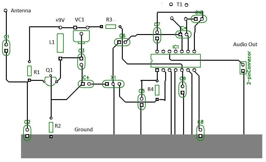
An appropriate vero board of 5cm* 7-1/2cm might be use to construct this undertaking. Now we are going to want a 14-pin IC socket for IC1.
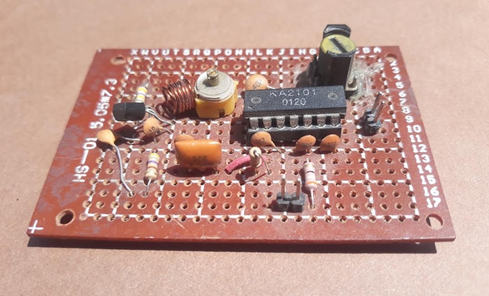
Now take a 14 pin IC socket and placed on a center of veroboard and solder it. Now place an IC1 KA2101 on IC socket.
Now take all the remainder parts and solder all by one after the other as given on circuit diagram with 25 watt soldering iron. You’ll want additionally to solder a 9 volts battery clip to attach a 9Volts battery. 5.5 MHz IFT1 coils might be made by winding 23 turns of 37 SWG wire on 8mm ferrite core. C* (68pF) is to attach on a main of 5.5MHz IFT coil.
Calibration and Adjustment
After putting all of the parts and soldering, subsequent you must do a calibration and adjustment.
Take 9 volts battery and join it to a 9V battery clip. Take a small B&W TV receiver and switch it ON and choose it on VHF vary. Convey an antenna (75 cm lengthy wire) close to to a B&W TV and tune a tunning till you’ll see a plain on raster. As quickly as you’ll see a plain raster on TV this may affirm you that RF amplifier, oscillator and mixer comprising transistor Q1 is working.
Subsequent is to verify if IC2 part is working or not. To do that Take AF Amplifier i.e. TBA 810, TBA 820 e.t.c. Now join it to an output of AF amplifier of IC 2 KA 2101. You’ll hear a hissing sound out of your AF amplifier. It will affirm that your FM radio receiver is working.
Subsequent step is to tune 5.5MHz IF stage. Take a 5.5 MHz IF sign generator and join its output to a capacitor C4 (47pF). Now take a plastic screw driver tune gently tune IFT coils T1. It’s best to hear a tone sound from an amplifier. It will confirms that 5.5MHz utilizing an IC1 KA 2101 part is working. Now disconnect 5.5MHz IF sign generator and reconnect C4 once more. Subsequent tune a VC1 2-22pF trimmer till you’ll hear a station clear and loud. You might also use an antenna 75cm in case you receiving weak sign. Take pleasure in listening you radio.*
PARTS-LIST
Resistors (all 1/4watt)
R1: 470K
R2: 470
R3:39
R4: 2K2
Capacitors
C1:.001uF
C2: .04uF
C3:10pF
C4: 47pF
C5: .04uF
C6:.001uF
C7:.01uF
C8: 15pF
C9:.04uF
C10:403
Ceramic Filter
X1: 3-pin 5.5MHz ceramic filter
Semiconductor:
Q1: BF494
IC1: KA 2101
Miscellaneous:
9Volts battery, 9 volts battery clip, 14-pin IC sockets, vero board 5*7/1cm, 2-pin connector T1 (5.5 MHz IFT coil)
Writer Prototype

[ad_2]