[ad_1]
Courtesy: Avnet
When deciding on parts for an EV charger design, semiconductors are the same old focus of consideration. Newer energy switching applied sciences, Silicon Carbide particularly, promise very low losses and general value financial savings. Passive parts can’t be forgotten. Using broad bandgap (WBG) switches resembling SiC MOSFETs presents extra alternatives for optimization. Passive parts within the energy practice might be smaller in dimension and decrease in weight, which comes with diminished value. These developments deliver passive applied sciences into play that might in any other case be unsuitable. The principle passives to contemplate are DC-link capacitors, filter inductors, and transformers.
The DC-link capacitor
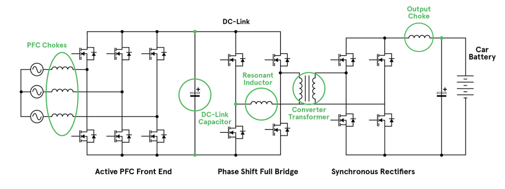
All on- and off-board EV chargers have related energy chains. They begin with an influence issue correction (PFC) stage adopted by an remoted DC-DC conversion stage. The output energy degree doesn’t change this primary structure, because the quickest 400kW+ roadside chargers will nonetheless sometimes comprise decrease energy modules in a stacked configuration. Every module will ship round 30kW, to cut back stress and supply redundancy. Every stage could also be bi-directional in fashionable designs and general would resemble any high-power AC-DC converter.
A Typical EV charger define with crucial passive parts highlighted

One of many foremost variations between a generic converter and an EV battery charger design is the sizing of the DC-link capacitor. This capacitor is positioned on the DC rail, or hyperlink, between the PFC and DC-DC conversion levels. The potential right here can be a voltage of round 650V as much as 1000V. In a general-purpose AC-DC converter, this capacitor is often sized for ‘hold-up’ time, sustaining the rail for sometimes 18/20ms after a mains failure. At 30kW, this would wish round 8,000 µF, occupying about 80 cubic inches (1300cm3). At this capability, aluminum electrolytics are probably the most economically viable possibility.
Maintain-up capacitance is calculated by equating the hold-up vitality required (hold-up time x output energy/effectivity), with the vitality expended because the capacitor voltage drops after AC failure from its regular degree to a drop-out degree, maybe from 650V to 500V. That’s, 30kW x 20ms/0.90 = (0.5 x C x 6502) – (0.5 x C x 5002) giving C = 7.7 mF.
In an EV charger software, hold-up just isn’t a problem. The scale of the DC-link capacitor is predicated on its skill to supply high-frequency ripple present for the DC-DC stage and sink ripple present from the PFC stage. The entire ripple voltage and temperature rise may also be components.
Probably the most appropriate half is decided by the Equal Sequence Resistance (ESR) and Equal Sequence Inductance (ESL) of the capacitor, in addition to its capacitance. Though excessive capacitance for hold-up just isn’t vital it’s nonetheless widespread to pick AL-electrolytics. Usually engineers will use massive capacitors in parallel, to realize the specified ESR and ESL. Due to the capacitors’ dimension, it may be troublesome to maintain complete connection resistance low with good ripple present sharing between the parts.
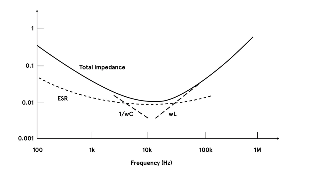
The entire impedance of an AL-electrolytic will sometimes attain its minimal at round 10kHz. That frequency is as a result of capacitance, ESL, and variation in ESR. This low frequency just isn’t a very good match when utilizing WBG gadgets, which change higher at a number of hundred kHz. The ESR of AL-electrolytics additionally rises strongly at low temperatures which could possibly be problematic at start-up, particularly in a battery charger software situated outdoors. On the different excessive, 105°C is often the utmost score for an AL electrolytic.
Switch curve of an AL electrolytic

For an alternative choice to AL-electrolytics, take a look at movie and multilayer ceramic capacitors (MLCCs). MLCCs have very low ESR and ESL, so the low impedance level happens at the next frequency. This larger frequency is extra appropriate when utilizing WBG gadgets. The MLCC additionally has an extended lifetime than AL-electrolytics, maybe 10x underneath the identical circumstances.
It’s now widespread to see movie capacitors used within the DC-link place. Movie varieties can be found rated to excessive voltages and function at temperatures of a minimum of 135°C. The widespread PCB-mount ‘field’ format used for MLCCs makes them simple to assemble with good packing density. They will additionally self-heal after over-voltage stress, not like AL-electrolytics.
Nevertheless, MLCCs are comparatively excessive value and low capacitance worth per package deal. Attaining excessive capacitance requires utilizing many in parallel. Some MLCCs are additionally comparatively fragile and inclined to substrate flexing. Nevertheless, some MLCCs designed particularly for DC-link purposes at the moment are out there, with fitted metallic frames round paralleled elements. This eases meeting and supplies some mechanical flexibility within the terminations.
Quantifying ripple present
Ripple present for a DC-link capacitor is troublesome to quantify. The worth relies on working circumstances, and summing the overall worth sunk from the PFC stage and sourced to the DC-DC stage just isn’t easy. If the levels will not be synchronized or if both stage is variable frequency, it’s more durable nonetheless to determine.
Simulation and bench measurements can be utilized, however as an approximation, for a DC hyperlink at 650V and 30kW load, the common present is about 50A permitting for inefficiencies. For a DC-DC responsibility cycle of 80%, that is about 25A rms sourced from the capacitor assuming a sq. wave. At a switching frequency of 100kHz and 10V rms ripple, solely about 4µF could be wanted if capacitive impedance dominates. If the capacitor ESR had been 10 milliohms, this could add an additional 0.25V rms of ripple. We may guess that the ripple from the PFC stage is of the identical order.
Regardless of these gross assumptions, it signifies that just a few tens of µF could be wanted and movie capacitors change into sensible if a number of are paralleled to realize the ripple present functionality. For instance, 4 paralleled 20µF/700V metalized polypropylene capacitors can deal with 62.5A rms complete ripple with an general ESR of lower than one milliohm, giving lower than 4 W complete dissipation at 50A rms ripple present. The general quantity is 8.5 cubic inches (139 cm3).
An AL-electrolytic answer, for related ripple present functionality could possibly be assembled from 10x 2700µF/400V elements, in a 5-parallel 2-series association, with about 85A ripple present score (10kHz) and an ESR of about 8 milliohms complete. At 50A rms ripple present, this could give about 20W of dissipation general.
Ripple voltage is far decrease than the movie capacitor answer, due to decrease capacitive impedance, however the general quantity could be 125 cubic inches (2060 cm3) or almost 15x bigger. Additional benefits of movie capacitors embrace a very low ESL of some tens of nH, including solely a volt or so to the ripple voltage waveform.
Evaluating a typical MLCC answer, three in parallel may obtain 50A rms ripple score and satisfactory capacitance for lower than 10V rms ripple. ESR could be round 2 milliohms complete and dissipation round 3W general. Low ESR and ESL are maintained as much as a frequency of a minimum of 1MHz. This makes MLCC a very good candidate for ultra-fast switching the place capacitance worth is much less vital. ESR and capacitance do differ nonetheless fairly strongly with temperature and bias voltage. Sometimes, three modules would occupy simply 0.8 cubic inches (13.25 cm3).
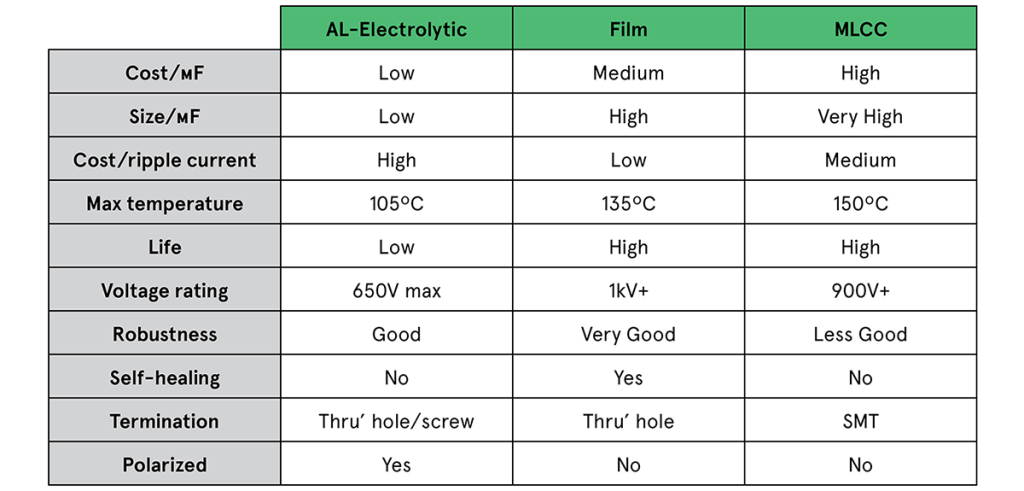
Indicative quantity pricing exhibits 4 of the movie elements would value round one quarter the worth of ten AL-electrolytics, whereas three MLCC modules could be about half the worth of the ten AL-electrolytics. In apply, derating can be utilized to capacitors of any kind, requiring additional parallel elements. That will apply extra so for the electrolytics. On this case, the distinction turns into much more putting. The desk exhibits the distinction in headline efficiency of movie, MLCC, and AL-electrolytic capacitors.
Evaluating capacitors for EV chargers

Magnetics in EV chargers
Magnetic parts in EV chargers are like all present in AC-DC converters, however the quick charger surroundings and the development towards WBG semiconductors influences the selection of fabrication approach. The principle parts to contemplate are the enter EMI filter, PFC inductor, DC-DC transformer, output choke, and any extra resonant inductors, relying on the converter topology getting used.
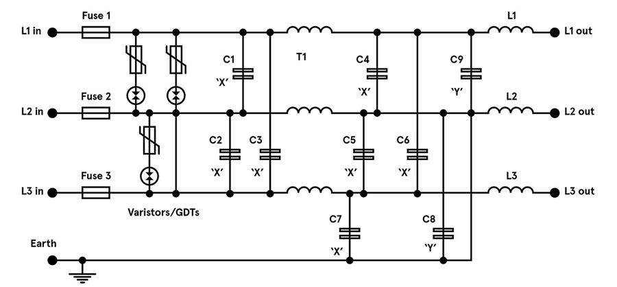
The EMI filter will comprise a minimum of one common-mode choke within the AC enter traces with windings phased in order that flux from line currents cancel. This permits excessive inductance for use with out threat of saturation. Excessive permeability ferrite cores are usually used however nano-crystalline materials is usually seen for optimum inductance.
Windings are spaced to realize voltage isolation and ideally in only a single layer, to maintain self-capacitance low and self-resonance excessive. Differential-mode chokes are additionally often vital, and these see flux from the complete line present. To keep away from saturation, they’re sometimes low inductance, wound on iron energy core toroids. Some common-mode choke designs add separation to their windings to intentionally introduce leakage flux, which acts as an built-in differential mode choke. Each common-mode and differential-mode chokes are wound with magnet wire on bobbins or headers for PCB mounting.

Magnetic part choice in EV chargers
The PFC choke operates at excessive frequency and its inductance worth is chosen to match the working mode of the stage; steady, discontinuous, or ‘boundary’. These modes commerce off semiconductor stress with potential EMI and choke dimension, and with the excessive peak currents current, a low efficient core permeability is required to keep away from saturation.
A powder core would produce extreme core losses, so the desire is a gapped ferrite. This could supply minimal loss on the working flux density and frequency, and on the anticipated working temperature. The part could possibly be of bobbin building, however a planar strategy might be sensible with PCB traces used as windings, giving low losses and a big floor space to assist dissipate warmth.
The DC-DC converter topology will invariably be a model of a ahead converter, sometimes a full-bridge, and infrequently a resonant kind on the energy ranges concerned. Planar transformer designs are widespread as they’re constant and straightforward to combine with the facility switches working at excessive frequency. Nevertheless, security isolation is required and the suitable creepage and clearance distances might be troublesome to realize with this building.
Generally, excessive main inductance is required, achieved with an ungapped high-permeability core, and, just like the PFC choke, the fabric is chosen for the bottom core losses. Resonant converters use an additional inductor that may be shaped from the leakage inductance of the primary transformer. This may be troublesome to manage and might restrict general efficiency, so usually the inductor is a separate part. The worth might be very low so it may conceivably be air-cored however is extra prone to make the most of a core to constrain the magnetic area and cut back interactions.
An output choke, if vital for the topology, is chosen in an identical technique to the PFC choke. A desired ripple present is specified, which units inductance for a given output voltage, responsibility cycle, and frequency. The DC output present flows by the choke, so a gapped ferrite is the traditional core answer. The part once more could possibly be a planar building in fashionable designs.
Conclusion
Passive parts can change into a restrict to the efficiency achieved in EV charger designs. There are selections of parts nonetheless which may leverage the traits of the newest semiconductor applied sciences to reduce losses and contribute to general discount in dimension, weight, and price.
As a worldwide chief in IP&E options, Avnet has a strong provider line card in all areas in addition to intensive design assist and demand creation companies. Our devoted IP&E specialists will help with all the things from provide chain must service group necessities.
[ad_2]