[ad_1]
JAMES KIM, Senior Semiconductor and Course of Integration Engineer | Lam Analysis
Asymmetries in wafer map defects are often handled as random manufacturing {hardware} defects. For instance, uneven wafer defects will be attributable to particles inadvertently deposited on a wafer throughout any variety of course of steps. On this article, I need to share a special mechanism that may trigger wafer defects. Specifically, that these defects will be structural defects which might be attributable to a biased deposition or etch course of.
It may be troublesome for a course of engineer to find out the reason for downstream structural defects situated at a particular wafer radius, significantly if these defects are situated in various instructions or at completely different areas on the wafer. As a wafer construction is fashioned, course of conduct at that location might fluctuate from different wafer areas primarily based upon the radial route and particular wafer location. Slight variations in processes at completely different wafer areas will be exaggerated by the buildup of different course of steps as you progress towards that location. As well as, course of efficiency variations (similar to variation in gear efficiency) can even trigger on-wafer structural variability.
On this research, structural defects might be nearly launched on a wafer to offer an instance of how structural defects will be created by variations in wafer location. We are going to then use our digital course of mannequin to establish an instance of a mechanism that may trigger most of these uneven wafer map defects.
Strategies

deposition on a tilted construction attributable to wafer warping
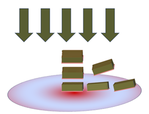
A 3D course of mannequin of a particular metallic stack (Cu/TaN/Ta) on a warped wafer was created utilizing SEMulator3D digital fabrication (Determine 1). After the 3D mannequin was generated, electrical evaluation of 49 websites on the wafer was accomplished.
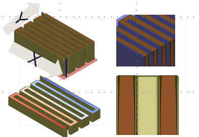
In our mannequin, an anisotropic barrier/liner (TaN/Ta) deposition course of was used. Attributable to wafer tilting, there have been TaN/Ta deposition variations seen throughout the simulated excessive side ratio metallic stack. To reduce the variety of variables within the mannequin, Cu deposition was assumed to fill in a super method (with out voids). Forty-nine (49) corresponding 3D fashions have been created at completely different areas on the wafer, to mirror variations in tilting as a consequence of wafer warping. Subsequent, electrical simulation was accomplished on these 3D fashions to watch metallic line resistance at every location. Serpentine metallic line patterns have been constructed into the mannequin, to assist simulate the projected electrical efficiency on the warped wafer at completely different factors on the identical radius, and throughout completely different instructions on the wafer (Determine 2).

Utilizing solely incoming construction and course of conduct, we are able to develop a behavioral course of mannequin and prolong our gadget efficiency predictions and behavioral pattern evaluation outdoors of our proposed course of window vary. Within the case of sophisticated processes with multiple mechanism or conduct, we are able to cut up processes into a number of steps and develop fashions for every particular person course of step. There might be phenomena or conduct in manufacturing that may’t be totally captured by any such course of modeling, however these fashions present helpful perception throughout course of window growth.
Outcomes
Of the 49 3D fashions, the fashions on the far fringe of the wafer have been closely tilted by wafer warpage. Apparently, not all the fashions on the similar wafer radius exhibited the identical conduct. This was because of the metallic sample design. With anisotropic deposition into excessive side ratio trenches, deposition in particular instructions was blocked at sure areas within the trenches (relying upon trench depth and tilt angle). This affected each the gadget construction and electrical conduct at completely different areas on the wafer.
Because the metallic traces have been extending throughout the x-axis, there have been minimal variations seen when tilting the wafer throughout the x-axis in our mannequin. X-axis tilting created solely a small distinction in thickness of the Ta/TaN relative to the Cu. Nevertheless, when the wafer was tilted within the y-axis utilizing our mannequin, the excessive side ratio wall blocked Ta/TaN deposition because of the deposition angle. This lowered the quantity of Ta/TaN deposition relative to Cu, which decreased the metallic resistance and positioned the resistance outdoors of our design specification.
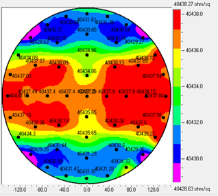
X-axis wafer tilting had little affect on the gadget construction. The resistance on the far fringe of the x-axis didn’t considerably change and remained in-spec. Y-axis wafer tilting had a extra important affect on the gadget construction. The resistance on the far fringe of the y-axis was outdoors of our electrical specification (Determine 3).

Conclusion
Despite the fact that wafer warpage happens in a round method as a consequence of amassed stress, sudden structural failures can happen in several radial instructions on the wafer as a consequence of variations in sample design and course of conduct throughout the wafer. From this research, we demonstrated that uneven constructions attributable to wafer warping can create top-bottom or left-right wafer efficiency variations, though processes have been uniformly utilized in a round distribution throughout the wafer.
Course of simulation can be utilized to higher perceive structural failures that may trigger efficiency variability at completely different wafer areas. A greater understanding of those structural failure mechanisms may help engineers enhance general wafer yield by taking corrective motion (similar to performing line scanning at particular wafer areas) or by adjusting particular course of home windows to attenuate uneven wafer defects.
[ad_2]